This is where automation comes in. Here is one easy project that can automatically switch ON at dusk and switch OFF at dawn a light. Let us call it simply as a NiteSwitch. It is fun to build and, when properly used, can save you a few bucks from your monthly electricity bills.
Warning: This project uses a circuit with direct connections to the AC mains. There exists a RISK OF ELECTRIC SHOCK, hence, I do not recommend this project to novice builders.
Shown in the above figure is the simplified block diagram of the NiteSwitch. It consists of three basic circuitry, the AC-DC converter, which convert the 220V AC mains to a low 6.8V DC voltage that is used to power the rest of the circuit, the Schmitt Trigger gate drive, and the AC Switch itself. The main sensing element is LDR R3, a resistor that changes its resistance when exposed to light. R4 provides a convenient means to adjust the turn ON sensitivity of the circuit to the desired brightness.
The full schematic of the NiteSwitch is shown in the figure above. AC mains voltage is reduced to a low voltage by C1, low enough to safely power the circuit. D1 and D2 converts the AC voltage to DC. R1 limits the inrush current and make the circuit more resistant to unwanted transients. C2 smoothens the converted DC, while D3 makes sure the converted DC voltage does not increase above 6.8 volts.
The component of interest here is the AC switch ACS108-5S. This device works like a TRIAC, switching ON and OFF the output according to the gate drive current. But unlike a TRIAC, the AC switch is immune from false switching that may be brought about by fast changes in the load current (voltage). In other words, it can switch inductive load, like small motors and solenoids, without the need for transients absorbing components as those needed by the TRIACs based circuit. This keeps the circuit simple and easy to build.
Also unlike its TRIAC relative, the AC switch will switch ON only when current flows out of the gate, necessitating the need for a negative voltage trigger referenced to the common pin.
The LDR resistance increases as the surrounding darkens. U1 checks this change by measuring the voltage across the LDR. If it becomes dark enough, U1 will trigger ON the AC switch Q2 by pulling a current from its gate. R7, R8 and R9 provides hysteresis to prevent U1 from entering a ‘undecided’ state. This state is when the ambient brightness falls to a level and the NiteSwitch can’t be sure whether it is dark enough or bright enough to switch the light. This otherwise unwanted state will result in a rapid switching ON and OFF, possibly damaging whatever is connected on the NiteSwitch output.
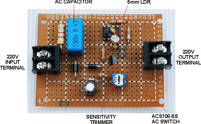
This picture shows how the circuit is assembled using a prototyping PCB. Major components are identified. Note the use of AC rated capacitor for C1. Do substitute with DC voltage rated capacitors!
The AC Switch Q2 pin out. Although ST Microelectronics stopped production of this component as of this date of writing, a lot of these are still in circulation, and will still be available many years from now. Complete component datasheet can be downloaded from ST site
It is easy to identify AC mains rated capacitors. These are usually adorned with a number of safety approval marks (e.g. UL, CSA, VDE, BS, etc). These capacitors are designed to to survive the harsh conditions present at AC mains, and are guaranteed not to burst in fire in case it fails.
The PCB underside, copper and wiring side, is shown in this photo. Most components are connected together by directly soldering once component lead to the other, or by solder bridging. Kaynar wires are used for the other connections. A heavier gauge wire (blue) is used for the AC switch path.
Application Note:
If the NiteSwitch is used for automatic illumination, make sure the LDR is shielded away from the light coming from the lamp the NiteSwitch is driving. Unexpected results may occur otherwise.
| Item | Qty | Description | Part Ref |
| 1 | 1 | 0u1 250VAC AC Capacitor | C1 |
| 2 | 1 | 100uF/16V | C2 |
| 3 | 1 | 0u1 25V Multilayer Ceramic | C3 |
| 4 | 2 | 1N4007 Rectifier | D1,D2 |
| 5 | 1 | 6v8 1/2w Zener Diode | D3 |
| 6 | 1 | 470R 1W Resistor | R1 |
| 7 | 1 | 1K 1/4W Resistor | R2 |
| 8 | 1 | CDS/LDR 5mm | R3 |
| 9 | 1 | 20K Trimmer Resistor | R4 |
| 10 | 1 | 2k2 1/4W Resistor | R5 |
| 11 | 1 | 470K 1/4W Resistor | R6 |
| 12 | 1 | 100K 1/4W Resistor | R7 |
| 13 | 2 | 10K 1/4W Resistor | R8,R9 |
| 14 | 1 | ACS108-5S AC Switch | Q2 |
| 15 | 1 | NJM2903D/LM2903 Dual Comparator IC | U1 |
| 16 | 1 | Prototyping PCB 5×7 | |
| Estimated component cost @ e-Gizmo: Less than P100.00 as of date of publication |


No comments:
Post a Comment